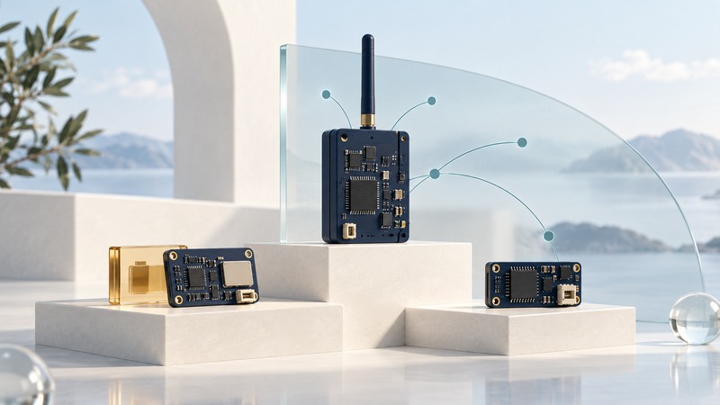
Choose a wireless mesh module by matching its radio, supported software stack, network role and application interface. A shared frequency or IEEE radio label establishes only part of compatibility. The useful selection test is two supported endpoints exchanging the data your application needs under the intended power and recovery conditions.
This guide is for developers comparing modules for a sensor or control prototype. Bring the intended data fields, reporting interval, available power, host interface and receiving system. Module selection becomes concrete once those requirements are written down.
Separate the layers in the product description
A module packages hardware such as a radio, processor, memory and antenna arrangement. Its physical and link layers define how signals and frames operate. A networking stack adds addressing, joining and forwarding behavior. The application then defines what a temperature reading or command means and how a peer interprets it.
Early sensor modules such as Crossbow's MICAz were associated with particular embedded software ecosystems. Treat such hardware and its period-specific stack as a historical combination. A modern Thread example is a separate implementation choice; an old 802.15.4 label alone establishes no Thread interoperability.
Scroll the table horizontally; keyboard users can focus it and use the arrow keys.
| Layer | Ask the supplier or documentation | Proof for the prototype |
|---|---|---|
| Radio and region | Which bands, physical modes, antenna options and regional conditions apply? | The exact SKU and antenna arrangement fit the intended installation. |
| Stack | Which protocol versions, SDK releases and roles are supported? | Buildable examples and documented compatibility with the receiving network. |
| Application | What messages, data models and commissioning credentials do peers require? | A peer can interpret the actual field, unit and status. |
| Host interface | Is this a programmable processor, network coprocessor or radio coprocessor? | The host has the required driver, protocol and resource budget. |
| Lifecycle | Who maintains updates, boot recovery and supported toolchains? | A recorded version can be rebuilt, installed and recovered. |
Match the network role to power
In OpenThread's current node-role primer, a forwarding node is termed a Mesh Extender. It forwards packets and keeps its radio on. An End Device primarily communicates with a parent, does not forward other nodes' traffic, and can reduce power by turning its radio off. The primer further distinguishes device capabilities and sleepy behavior.
That distinction changes placement and energy planning. A battery sensor that sleeps between reports contributes measurements, while suitably powered forwarding nodes supply the path through the network. A Thread Border Router connects Thread with another IP network; choose that function separately from the question of which nearby node forwards mesh traffic.
Record the actual application's wake, receive, transmit and idle behavior. A low sleep-current specification describes one state. Battery life also depends on reporting, retries, parent interaction, sensor warm-up and the regulator. Use measured current over the whole duty cycle once a candidate reaches the bench.
Decide where the application runs
If the module runs your application, check available flash and RAM after enabling the chosen stack, update mechanism and security features. Confirm sensor interfaces, pin voltage limits and the board's documented wiring before connecting hardware.
If a separate host runs the application, establish what crosses UART, SPI or USB. Raw radio access, a network-coprocessor protocol and a vendor command interface require different host software. Pin names and connector compatibility alone leave that software dependency unresolved.
Fictional selection: a battery sensor reports one temperature value every minute, while a mains-powered room node forwards traffic. Candidate A has a maintained sleepy-end-device example and the required sensor interface. Candidate B exposes only a radio-coprocessor interface requiring a host processor the sensor design lacks. A is the clearer first sensor prototype; B may fit a host-based border-router design after its driver and stack support are checked. This is an example of role fit, not a ranking of real products.
Prove a supported pair before designing a board
- Record exact module and development-board revisions, SDK, stack release, antenna and peer firmware.
- Build the vendor's supported joining example and confirm the intended node role.
- Send an application value with an explicit unit and source identity. Confirm the receiving application understands it.
- Restart an endpoint and then a parent or forwarding node in the lab. Observe rejoining time, missing data and any credential intervention.
- Measure the complete reporting cycle's current and memory use with the application features enabled.
- Demonstrate a supported firmware update and a documented recovery path before committing to custom hardware.
Use a local record of the observed results and failures to choose the next design. For the first end-to-end firmware and reading exercise, see the wireless sensor prototype guide. For the larger monitoring deployment, use the sensor-system pilot guide.